Solidworks Simulation Tutorial With Heat Exchanger Efficiency
Solidworks Flow Simulation can be used to study the fluid flow and heat transfer for a wide variety of engineering equipment. In this example we use Solidworks Flow Simulation to determine the efficiency of a counterflow heat exchanger and to observe the temperature and flow patterns inside of it. With Solidworks Flow Simulation the determination of heat exchanger efficiency is straightforward and by investigating the flow and temperature patterns, the design engineer can gain insight into the physical processes involved thus giving guidance for
improvements to the design.

A convenient measure of heat exchanger performance is its “efficiency” in transferring a given amount of heat from one fluid at higher temperature to another fluid at lower temperature. The efficiency can be determined if the temperatures at all flow openings are known. In Solidworks Flow Simulation the temperatures at the fluid inlets are specified and the temperatures at the outlets can be easily determined. Heat exchanger efficiency is defined as follows:


Open the Model Solidworks Simulation Tutorial With Heat Exchanger Efficiency
Click File, Open. In the Open dialog box, browse to the Heat Exchanger.SLDASM assembly located in the Tutorial 3 - Heat Exchanger folder and click Open (or doubleclick the assembly). Alternatively, you can drag and drop the Heat Exchanger.SLDASM file to an empty area of SolidWorks window.
Get File Pdf Solidworks Simulation Tutorial With Heat Exchanger Efficiency
 Read More
Add your Comment
1 comments
Read More
Add your Comment
1 comments
Determination of Hydraulic Loss in Solidworks Flow Simulation
Determination of Hydraulic Loss in Solidworks Flow Simulation
In engineering practice the hydraulic loss of pressure head in any piping system is traditionally split into two components: the loss due to friction along straight pipe sections and the local loss due to local pipe features, such as bends, T-pipes, various cocks, valves, throttles, etc. Being determined, these losses are summed to form the total hydraulic loss. Generally, there are no problems in engineering practice to determine the friction loss in a piping system since relatively simple formulae based on theoretical and experimental investigations exist. The other matter is the local hydraulic loss (or so-called local drag). Here usually only experimental data are available, which are always restricted due to their nature, especially taking into account the wide variety of pipe shapes (not only existing, but also advanced) and devices, as well as the substantially complicated flow patterns in them.
Flow Simulation presents an alternative approach to the traditional problems associated with determining this kind of local drag, allowing you to predict computationally almost any local drag in a piping system within good accuracy. Click File, Open. In the Open dialog box, browse to the Valve.SLDPRT model located in the Tutorial 1 - Hydraulic Loss folder and click Open (or double-click the part). Alternatively, you can drag and drop the Valve.SLDPRT file to an empty area of the SolidWorks window.
Model Description
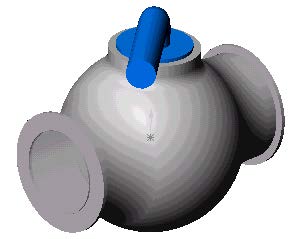

Internal flow analyses deal with flows inside pipes, tanks, HVAC systems, etc. The fluid enters a model at the inlets and exits the model through outlets. To perform an internal analysis all the model openings must be closed with lids, which are needed to specify inlet and outlet flow boundary conditions on them. In any case, the internal model space filled with a fluid must be fully closed. You simply create lids as additional extrusions covering the openings. In this example the lids are semi-transparent allowing a view into the valve
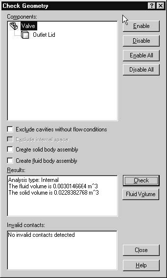
The Check Geometry tool allows you to calculate the total fluid and solid volumes, check bodies for possible geometry problems (i.e. invalid contact) and visualize the fluid area and solid body as separate models. The first step is to create a new Flow Simulation project
1 Click Flow Simulation, Project, Wizard. The project wizard guides you through the definition of a new Flow Simulation project.
2 In the Project Configuration dialog box, click Use current. Each Flow Simulation project is associated with a SolidWorks configuration. You can attach the project either to the current SolidWorks configuration or create a new SolidWorks configuration based on the current one. Click Next.
3 In the Unit System dialog box you can select the desired system of units for both input and output (results). For this project use the International System SI by default. Click Next.
4 In the Analysis Type dialog box you can select either Internal or External type of the flow analysis. To disregard closed internal spaces not involved in the internal analysis, you select Exclude cavities without flow conditions. The Reference axis of the global coordinate system (X, Y or Z) is used for specifying data in a tabular or formula form in a cylindrical coordinate system based on this axis.
This dialog also allows you to specify advanced physical features you may want to take into account (heat conduction in solids, gravitational effects, time-dependent problems, surface-to-surface radiation, rotation). Specify Internal type and accept the other default settings.
Click Next.
Since we use water in this project, open the Liquids folder and double-click the Water item. Engineering Database contains numerical physical information on a wide variety of gas, liquid and solid substances as well as radiative surfaces. You can also use the Engineering Database to specify a porous medium. The Engineering Database contains pre-defined unit systems. It also contains fan curves defining volume or mass flow rate versus static pressure difference for selected industrial fans. You can easily create your own substances, units, fan curves or specify a custom parameter you want to visualize.
Click Next.
6 Since we do not intend to calculate heat conduction in solids, in the Wall Conditions dialog box you can specify the thermal wall boundary conditions applied by default to all the model walls contacting with the fluid. For this project accept the default Adiabatic wall feature denoting that all the model walls are heat-insulated. In this project we will not consider rough walls. Click Next.
7 In the Initial Conditions dialog box specify initial values of the flow parameters. For steady internal problems, the specification of these values closer to the expected flow field will reduce the analysis convergence time.
For steady flow problems Flow Simulation iterates until the solution converges. For unsteady (transient, or time-dependent) problems Flow Simulation marches in time for a period you specify. For this project use the default values. Click Next
8 In the Results and Geometry Resolution dialog box you can control the analysis accuracy as well as the mesh settings and, through them, the required computer resources (CPU time and memory). For this project accept the default result resolution level 3.
Result Resolution governs the solution accuracy via mesh settings and conditions of finishing the calculation that can be interpreted as resolution of calculation results. The higher the Result Resolution, the finer the mesh and the stricter the convergence criteria. Naturally, higher Result Resolution requires more computer resources (CPU time and memory).

Flow Simulation calculates the default minimum gap size and minimum wall thickness using information about the overall model dimensions, the computational domain, and faces on which you specify conditions and goals. However, this information may be insufficient to recognize relatively small gaps and thin model walls. This may cause inaccurate results. In these cases, the Minimum gap size and Minimum wall thickness must be specified manually. Click Finish.
Read More
Add your Comment
0
comments
Create a Flow Simulation Project in Solidworks
In Flow Simulation Project in Solidworks we consider flow in a section of an automobile exhaust pipe, whose exhaust
flow is resisted by two porous bodies serving as catalysts for transforming harmful carbon
monoxide into carbon dioxide.
Open the SolidWorks Model
1 Click File, Open.
2 In the Open dialog box, browse to theCatalyst.SLDASM assembly located inthe First Steps - Porous Media folderand click Open (or double-click theassembly). Alternatively, you can dragand drop the Catalyst.SLDASM file to an empty area of SolidWorks window.

When designing an automobile catalytic converter, the engineer faces a compromise between minimizing the catalyst's resistance to the exhaust flow while maximizing the catalyst's internal surface area and duration that the exhaust gases are in contact with that surface area. Therefore, a more uniform distribution of the exhaust mass flow rate over the catalyst's cross sections favors its serviceability
. The porous media capabilities of Flow Simulation are used to simulate each catalyst, which allows you to model the volume that the catalyst occupies as a distributed resistance instead of discretely modeling all of the individual passages within the catalyst, which would be impractical or even impossible.
Here, as a Flow Simulation tutorial example we consider the influence of the catalysts' porous medium permeability type (isotropic and unidirectional media of the same resistance to flow) on the exhaust mass flow rate distribution over the catalysts' cross sections. We will observe the latter through the behavior of the exhaust gas flow trajectories distributed uniformly over the model's inlet and passing through the porous catalysts. Additionally, by coloring the flow trajectories by the flow velocity the exhaust gas residence time in the porous catalysts can be estimated, which is also important from the catalyst effectiveness viewpoint.
Read More
Add your Comment
0
comments
Boundary Conditions Solidworks Flow Simulation Tutorial
Boundary Conditions Solidworks Flow Simulation Tutorial help you learn something
A boundary condition is required anywhere fluid enters or exits the system and can be
set as a Pressure, Mass Flow, Volume Flow or Velocity.
1 In the Flow right-click the Boundary Conditions icon

Simulation Analysis Tree,

shown. (To access the inner face, right-click
the Lid <1> in the graphics area and choose
Select Other , hover the pointer over
items in the list of items until the inner face
is highlighted, then click the left mouse
button).


.jpg)
appears in the Flow Simulation Analysis tree.
With the definition just made, we told Flow Simulation that at this opening 0.5
kilogram of water per second is flowing into the valve. Within this dialog box we can
also specify a swirl to the flow, a non-uniform profile and time dependent properties to
the flow. The mass flow at the outlet does not need to be specified due to the
conservation of mass; mass flow in equals mass flow out. Therefore another different
condition must be specified. An outlet pressure should be used to identify this
condition.
shown. (To access the inner face, right-click
the Lid <2> in the graphics area and choose
Select Other , hover the pointer over items
in the list of items until the inner face is
highlighted, then click the left mouse button).
7 In the Flow Simulation Analysis Tree, rightclick
the Boundary Conditions icon and
select Insert Boundary Condition.


Turbulence Parameters, Boundary Layer and Options group boxes.
10 Click OK . The new Static Pressure 1 item appears in
the Flow Simulation Analysis tree.
With the definition just made, we told Flow Simulation that at this opening the fluid exits the model to an area of static atmospheric pressure. Within this dialog box we can also set time dependent properties to the pressure.
Read More
Add your Comment
0
comments
First Steps - Ball Valve Design in Solidworks Flow Simulation tutorial
Flow Simulation solidworks tutorial
This First Steps tutorial covers the flow of water through a ball valve assembly before and
after some design changes. The objective is to show how easy fluid flow simulation can be
using Solidworks Flow Simulation and how simple it is to analyze design variations. These two factors make Solidworks Flow Simulation the perfect tool for engineers who want to test the impact of their design changes.

1 Copy the First Steps - Ball Valve folder into your working directory and ensure that the files are not read-only since Flow Simulation will save input data to these files. Run Flow Simulation.
2 Click File, Open. In the Open dialog box, browse to the
Ball Valve.SLDASM assembly located in the First Steps - Ball Valve folder and click Open (or double-click the assembly). Alternatively, you can drag and drop the Ball Valve.SLDASM file to an empty area of SolidWorks window. Make sure, that the default configuration is the active one.
* This is a ball valve. Turning the handle closes or opens
the valve. The mate angle controls the opening angle.
3 Show the lids by clicking the features in the FeatureManager design tree (Lid <1> and Lid <2>).
* We utilize this model for the Flow Simulation simulation without many significant
changes. The user simply closes the interior volume using extrusions we call lids. In
this example the lids are made semi-transparent so one may look into the valve.
Create a Flow Simulation Project

Wizard.
2 Once inside the Wizard, select Create
new in order to create a new
configuration and name it Project 1.
* Solidworks Flow Simulation will create a new configuration and store all data in a
new folder.
Click Next.

project). Please keep in mind that after
finishing the Wizard you may change
the unit system at any time by clicking
Flow Simulation, Units.
* Within Flow Simulation, there are
several predefined systems of units. You
can also define your own and switch
between them at any time.
Click Next.

Do not include any physical features.
*We want to analyze the flow through the
structure. This is what we call an internal
analysis. The alternative is an external
analysis, which is the flow around an
object. In this dialog box you can also
choose to ignore cavities that are not
relevant to the flow analysis, so that Flow
Simulation will not waste memory and
CPU resources to take them into account.
*Not only will Flow Simulation calculate the fluid flow, but can also take into account
heat conduction within the solid(s) including surface-to-surface radiation. Transient
(time dependent) analyses are also possible. Gravitational effects can be included for
natural convection cases. Analysis of rotating equipment is one more option available.
We skip all these features, as none of them is needed in this simple example.
Click Next.

and choose Water as the fluid. You can
either double-click Water or select the
item in the tree and click Add.
* Flow Simulation is capable of calculating
fluids of different types in one analysis,
but fluids must be separated by the walls.
A mixing of fluids may be considered only
if the fluids are of the same type.
*Solidworks Flow Simulation has an integrated database containing several liquids, gases and
solids. Solids are used for conduction in conjugate heat conduction analyses. You can
easily create your own materials. Up to ten liquids or gases can be chosen for each
analysis run.
*Solidworks Flow Simulation can calculate analyses with any flow type: Turbulent only, Laminar
only or Laminar and Turbulent. The turbulent equations can be disregarded if the flow
is entirely laminar. Solidworks Flow Simulation can also handle low and high Mach number
compressible flows for gases. For this demonstration we will perform a fluid flow
simulation using a liquid and will keep the default flow characteristics.
Click Next.

conditions.
* Since we did not choose to consider heat
conduction within the solids, we have an
option of defining a value of heat
conduction for the surfaces in contact with
the fluid. This step is the place to set the
default wall type. Leave the default
Adiabatic wall specifying the walls are
perfectly insulated.
*You can also specify the desired wall roughness value applied by default to all model
walls. To set the roughness value for a specific wall, you can define a Real Wall
boundary condition. The specified roughness value is the Rz value.
7 Click Next accepting the default for the initial conditions.
* On this step we may change the default settings for pressure, temperature and velocity. The closer these values are set to the final values determined in the analysis, the quicker the analysis will finish. Since we do not have any knowledge of the expected final values, we will not modify them for this demonstration.

Resolution.
* Result Resolution is a measure of the desired level of accuracy of the results. It controls
not only the resolution of the mesh, but also sets many parameters for the solver, e.g.
the convergence criteria. The higher the Result Resolution, the finer the mesh will be
and the stricter the convergence criteria will be set. Thus, Result Resolution determines
the balance between results precision and computation time. Entering values for the
minimum gap size and minimum wall thickness is important when you have small
features. Setting these values accurately ensures your small features are not “passed
over” by the mesh. For our model we type the value of the minimum flow passage as the
minimum gap size.
Click the Manual specification of the minimum gap size box. Enter the value 0.0093 m for the minimum flow passage.
Click Finish.
Read More
Add your Comment
3
comments
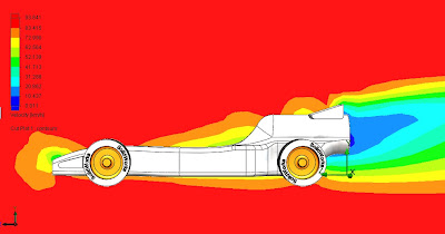
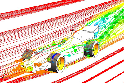
Design with SolidWorks flow simulation

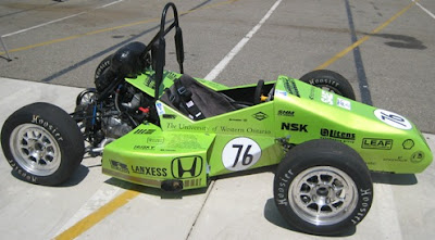
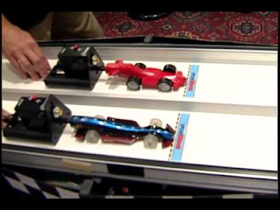
 Read More
Add your Comment
0
comments
Read More
Add your Comment
0
comments
create the intersection between a loft and a sweep in solidworks
A customer requested help creating the intersection between a loft and a sweep. He is working on a hairdryer and had already created the profiles to generate the lofted solid.

The first thing that came to mind was to just extrude the handle up to the next surface. You could also modify by adding another profile to the loft so that it would not result in multiple bodies.

Then, you can easily add any type of fillet that you want to create a nice looking transition. Shell the part out and it's done. Well, not really done, but well on your way.

Any other ideas to model this part better? Just add your comment.
Read More
Add your Comment
0
comments


