First Steps - Ball Valve Design in Solidworks Flow Simulation tutorial
Flow Simulation solidworks tutorial
This First Steps tutorial covers the flow of water through a ball valve assembly before and
after some design changes. The objective is to show how easy fluid flow simulation can be
using Solidworks Flow Simulation and how simple it is to analyze design variations. These two factors make Solidworks Flow Simulation the perfect tool for engineers who want to test the impact of their design changes.
1 Copy the First Steps - Ball Valve folder into your working directory and ensure that the files are not read-only since Flow Simulation will save input data to these files. Run Flow Simulation.
2 Click File, Open. In the Open dialog box, browse to the
Ball Valve.SLDASM assembly located in the First Steps - Ball Valve folder and click Open (or double-click the assembly). Alternatively, you can drag and drop the Ball Valve.SLDASM file to an empty area of SolidWorks window. Make sure, that the default configuration is the active one.
* This is a ball valve. Turning the handle closes or opens
the valve. The mate angle controls the opening angle.
3 Show the lids by clicking the features in the FeatureManager design tree (Lid <1> and Lid <2>).
* We utilize this model for the Flow Simulation simulation without many significant
changes. The user simply closes the interior volume using extrusions we call lids. In
this example the lids are made semi-transparent so one may look into the valve.
Create a Flow Simulation Project
1 Click Flow Simulation, Project,
Wizard.
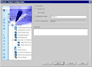
2 Once inside the Wizard, select Create
new in order to create a new
configuration and name it Project 1.
* Solidworks Flow Simulation will create a new configuration and store all data in a
new folder.
Click Next.
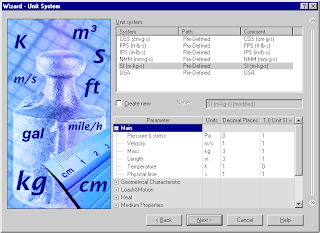
3 Choose the system of units (SI for this
project). Please keep in mind that after
finishing the Wizard you may change
the unit system at any time by clicking
Flow Simulation, Units.
* Within Flow Simulation, there are
several predefined systems of units. You
can also define your own and switch
between them at any time.
Click Next.
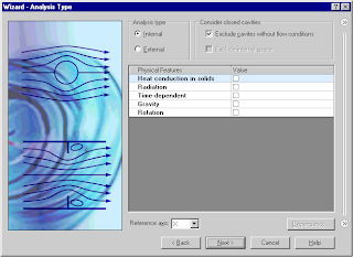
4 Leave the default Internal analysis type.
Do not include any physical features.
*We want to analyze the flow through the
structure. This is what we call an internal
analysis. The alternative is an external
analysis, which is the flow around an
object. In this dialog box you can also
choose to ignore cavities that are not
relevant to the flow analysis, so that Flow
Simulation will not waste memory and
CPU resources to take them into account.
*Not only will Flow Simulation calculate the fluid flow, but can also take into account
heat conduction within the solid(s) including surface-to-surface radiation. Transient
(time dependent) analyses are also possible. Gravitational effects can be included for
natural convection cases. Analysis of rotating equipment is one more option available.
We skip all these features, as none of them is needed in this simple example.
Click Next.
5 In the Fluids tree expand the Liquids item
and choose Water as the fluid. You can
either double-click Water or select the
item in the tree and click Add.
* Flow Simulation is capable of calculating
fluids of different types in one analysis,
but fluids must be separated by the walls.
A mixing of fluids may be considered only
if the fluids are of the same type.
*Solidworks Flow Simulation has an integrated database containing several liquids, gases and
solids. Solids are used for conduction in conjugate heat conduction analyses. You can
easily create your own materials. Up to ten liquids or gases can be chosen for each
analysis run.
*Solidworks Flow Simulation can calculate analyses with any flow type: Turbulent only, Laminar
only or Laminar and Turbulent. The turbulent equations can be disregarded if the flow
is entirely laminar. Solidworks Flow Simulation can also handle low and high Mach number
compressible flows for gases. For this demonstration we will perform a fluid flow
simulation using a liquid and will keep the default flow characteristics.
Click Next.
6. Click Next accepting the default wall
conditions.
* Since we did not choose to consider heat
conduction within the solids, we have an
option of defining a value of heat
conduction for the surfaces in contact with
the fluid. This step is the place to set the
default wall type. Leave the default
Adiabatic wall specifying the walls are
perfectly insulated.
*You can also specify the desired wall roughness value applied by default to all model
walls. To set the roughness value for a specific wall, you can define a Real Wall
boundary condition. The specified roughness value is the Rz value.
7 Click Next accepting the default for the initial conditions.
* On this step we may change the default settings for pressure, temperature and velocity. The closer these values are set to the final values determined in the analysis, the quicker the analysis will finish. Since we do not have any knowledge of the expected final values, we will not modify them for this demonstration.
8 Accept the default for the Result Solidworks Flow Simulation
Resolution.
* Result Resolution is a measure of the desired level of accuracy of the results. It controls
not only the resolution of the mesh, but also sets many parameters for the solver, e.g.
the convergence criteria. The higher the Result Resolution, the finer the mesh will be
and the stricter the convergence criteria will be set. Thus, Result Resolution determines
the balance between results precision and computation time. Entering values for the
minimum gap size and minimum wall thickness is important when you have small
features. Setting these values accurately ensures your small features are not “passed
over” by the mesh. For our model we type the value of the minimum flow passage as the
minimum gap size.
Click the Manual specification of the minimum gap size box. Enter the value 0.0093 m for the minimum flow passage.
Click Finish.
Tags: Flow Simulation solidworks tutorial, SolidWorks Simulation Tutorials
Subscribe to:
Post Comments (Atom)


Share your views...
3 Respones to "First Steps - Ball Valve Design in Solidworks Flow Simulation tutorial "
We have set up sales departments and after service spots in large and middle cities throughout China. We will success in providing our perfect quanlity guarantee and best after sales service for our Anix production. Anix Valve USA
June 14, 2015 at 7:50 PM
Great article Lot's of information to Read...Great Man Keep Posting and update to People..Thanks ball valve manufacturer
July 18, 2017 at 4:55 PM
Very useful post. This is my first time i visit here. I found so many interesting stuff in your blog especially its discussion. Really its great article. Keep it up.
valves manufacturer
November 18, 2018 at 7:30 AM
Post a Comment