Solidworks Simulation Tutorial With Heat Exchanger Efficiency
Solidworks Flow Simulation can be used to study the fluid flow and heat transfer for a wide variety of engineering equipment. In this example we use Solidworks Flow Simulation to determine the efficiency of a counterflow heat exchanger and to observe the temperature and flow patterns inside of it. With Solidworks Flow Simulation the determination of heat exchanger efficiency is straightforward and by investigating the flow and temperature patterns, the design engineer can gain insight into the physical processes involved thus giving guidance for
improvements to the design.

A convenient measure of heat exchanger performance is its “efficiency” in transferring a given amount of heat from one fluid at higher temperature to another fluid at lower temperature. The efficiency can be determined if the temperatures at all flow openings are known. In Solidworks Flow Simulation the temperatures at the fluid inlets are specified and the temperatures at the outlets can be easily determined. Heat exchanger efficiency is defined as follows:


Open the Model Solidworks Simulation Tutorial With Heat Exchanger Efficiency
Click File, Open. In the Open dialog box, browse to the Heat Exchanger.SLDASM assembly located in the Tutorial 3 - Heat Exchanger folder and click Open (or doubleclick the assembly). Alternatively, you can drag and drop the Heat Exchanger.SLDASM file to an empty area of SolidWorks window.
Get File Pdf Solidworks Simulation Tutorial With Heat Exchanger Efficiency
Determination of Hydraulic Loss in Solidworks Flow Simulation
Determination of Hydraulic Loss in Solidworks Flow Simulation
In engineering practice the hydraulic loss of pressure head in any piping system is traditionally split into two components: the loss due to friction along straight pipe sections and the local loss due to local pipe features, such as bends, T-pipes, various cocks, valves, throttles, etc. Being determined, these losses are summed to form the total hydraulic loss. Generally, there are no problems in engineering practice to determine the friction loss in a piping system since relatively simple formulae based on theoretical and experimental investigations exist. The other matter is the local hydraulic loss (or so-called local drag). Here usually only experimental data are available, which are always restricted due to their nature, especially taking into account the wide variety of pipe shapes (not only existing, but also advanced) and devices, as well as the substantially complicated flow patterns in them.
Flow Simulation presents an alternative approach to the traditional problems associated with determining this kind of local drag, allowing you to predict computationally almost any local drag in a piping system within good accuracy. Click File, Open. In the Open dialog box, browse to the Valve.SLDPRT model located in the Tutorial 1 - Hydraulic Loss folder and click Open (or double-click the part). Alternatively, you can drag and drop the Valve.SLDPRT file to an empty area of the SolidWorks window.
Model Description
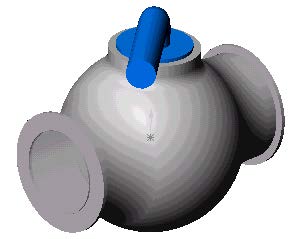

Internal flow analyses deal with flows inside pipes, tanks, HVAC systems, etc. The fluid enters a model at the inlets and exits the model through outlets. To perform an internal analysis all the model openings must be closed with lids, which are needed to specify inlet and outlet flow boundary conditions on them. In any case, the internal model space filled with a fluid must be fully closed. You simply create lids as additional extrusions covering the openings. In this example the lids are semi-transparent allowing a view into the valve
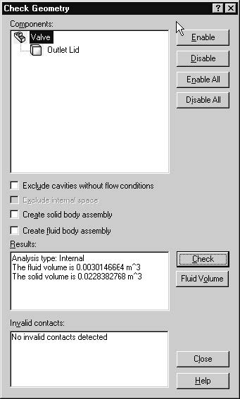
The Check Geometry tool allows you to calculate the total fluid and solid volumes, check bodies for possible geometry problems (i.e. invalid contact) and visualize the fluid area and solid body as separate models. The first step is to create a new Flow Simulation project
1 Click Flow Simulation, Project, Wizard. The project wizard guides you through the definition of a new Flow Simulation project.
2 In the Project Configuration dialog box, click Use current. Each Flow Simulation project is associated with a SolidWorks configuration. You can attach the project either to the current SolidWorks configuration or create a new SolidWorks configuration based on the current one. Click Next.
3 In the Unit System dialog box you can select the desired system of units for both input and output (results). For this project use the International System SI by default. Click Next.
4 In the Analysis Type dialog box you can select either Internal or External type of the flow analysis. To disregard closed internal spaces not involved in the internal analysis, you select Exclude cavities without flow conditions. The Reference axis of the global coordinate system (X, Y or Z) is used for specifying data in a tabular or formula form in a cylindrical coordinate system based on this axis.
This dialog also allows you to specify advanced physical features you may want to take into account (heat conduction in solids, gravitational effects, time-dependent problems, surface-to-surface radiation, rotation). Specify Internal type and accept the other default settings.
Click Next.
Since we use water in this project, open the Liquids folder and double-click the Water item. Engineering Database contains numerical physical information on a wide variety of gas, liquid and solid substances as well as radiative surfaces. You can also use the Engineering Database to specify a porous medium. The Engineering Database contains pre-defined unit systems. It also contains fan curves defining volume or mass flow rate versus static pressure difference for selected industrial fans. You can easily create your own substances, units, fan curves or specify a custom parameter you want to visualize.
Click Next.
6 Since we do not intend to calculate heat conduction in solids, in the Wall Conditions dialog box you can specify the thermal wall boundary conditions applied by default to all the model walls contacting with the fluid. For this project accept the default Adiabatic wall feature denoting that all the model walls are heat-insulated. In this project we will not consider rough walls. Click Next.
7 In the Initial Conditions dialog box specify initial values of the flow parameters. For steady internal problems, the specification of these values closer to the expected flow field will reduce the analysis convergence time.
For steady flow problems Flow Simulation iterates until the solution converges. For unsteady (transient, or time-dependent) problems Flow Simulation marches in time for a period you specify. For this project use the default values. Click Next
8 In the Results and Geometry Resolution dialog box you can control the analysis accuracy as well as the mesh settings and, through them, the required computer resources (CPU time and memory). For this project accept the default result resolution level 3.
Result Resolution governs the solution accuracy via mesh settings and conditions of finishing the calculation that can be interpreted as resolution of calculation results. The higher the Result Resolution, the finer the mesh and the stricter the convergence criteria. Naturally, higher Result Resolution requires more computer resources (CPU time and memory).

Flow Simulation calculates the default minimum gap size and minimum wall thickness using information about the overall model dimensions, the computational domain, and faces on which you specify conditions and goals. However, this information may be insufficient to recognize relatively small gaps and thin model walls. This may cause inaccurate results. In these cases, the Minimum gap size and Minimum wall thickness must be specified manually. Click Finish.
Create a Flow Simulation Project in Solidworks
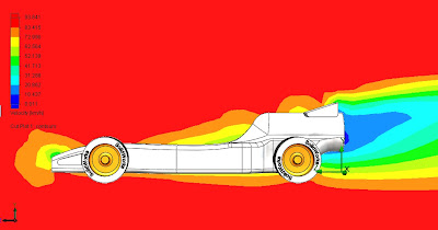
In Flow Simulation Project in Solidworks we consider flow in a section of an automobile exhaust pipe, whose exhaust
flow is resisted by two porous bodies serving as catalysts for transforming harmful carbon
monoxide into carbon dioxide.
Open the SolidWorks Model
1 Click File, Open.
2 In the Open dialog box, browse to theCatalyst.SLDASM assembly located inthe First Steps - Porous Media folderand click Open (or double-click theassembly). Alternatively, you can dragand drop the Catalyst.SLDASM file to an empty area of SolidWorks window.

When designing an automobile catalytic converter, the engineer faces a compromise between minimizing the catalyst's resistance to the exhaust flow while maximizing the catalyst's internal surface area and duration that the exhaust gases are in contact with that surface area. Therefore, a more uniform distribution of the exhaust mass flow rate over the catalyst's cross sections favors its serviceability
. The porous media capabilities of Flow Simulation are used to simulate each catalyst, which allows you to model the volume that the catalyst occupies as a distributed resistance instead of discretely modeling all of the individual passages within the catalyst, which would be impractical or even impossible.
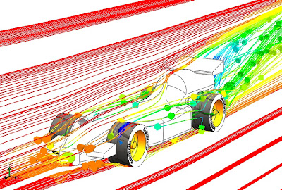
Here, as a Flow Simulation tutorial example we consider the influence of the catalysts' porous medium permeability type (isotropic and unidirectional media of the same resistance to flow) on the exhaust mass flow rate distribution over the catalysts' cross sections. We will observe the latter through the behavior of the exhaust gas flow trajectories distributed uniformly over the model's inlet and passing through the porous catalysts. Additionally, by coloring the flow trajectories by the flow velocity the exhaust gas residence time in the porous catalysts can be estimated, which is also important from the catalyst effectiveness viewpoint.
Boundary Conditions Solidworks Flow Simulation Tutorial
Boundary Conditions Solidworks Flow Simulation Tutorial help you learn something
A boundary condition is required anywhere fluid enters or exits the system and can be
set as a Pressure, Mass Flow, Volume Flow or Velocity.
1 In the Flow right-click the Boundary Conditions icon

Simulation Analysis Tree,

shown. (To access the inner face, right-click
the Lid <1> in the graphics area and choose
Select Other , hover the pointer over
items in the list of items until the inner face
is highlighted, then click the left mouse
button).


appears in the Flow Simulation Analysis tree.
With the definition just made, we told Flow Simulation that at this opening 0.5
kilogram of water per second is flowing into the valve. Within this dialog box we can
also specify a swirl to the flow, a non-uniform profile and time dependent properties to
the flow. The mass flow at the outlet does not need to be specified due to the
conservation of mass; mass flow in equals mass flow out. Therefore another different
condition must be specified. An outlet pressure should be used to identify this
condition.
shown. (To access the inner face, right-click
the Lid <2> in the graphics area and choose
Select Other , hover the pointer over items
in the list of items until the inner face is
highlighted, then click the left mouse button).
7 In the Flow Simulation Analysis Tree, rightclick
the Boundary Conditions icon and
select Insert Boundary Condition.


Turbulence Parameters, Boundary Layer and Options group boxes.
10 Click OK . The new Static Pressure 1 item appears in
the Flow Simulation Analysis tree.
With the definition just made, we told Flow Simulation that at this opening the fluid exits the model to an area of static atmospheric pressure. Within this dialog box we can also set time dependent properties to the pressure.
First Steps - Ball Valve Design in Solidworks Flow Simulation tutorial
Flow Simulation solidworks tutorial
This First Steps tutorial covers the flow of water through a ball valve assembly before and
after some design changes. The objective is to show how easy fluid flow simulation can be
using Solidworks Flow Simulation and how simple it is to analyze design variations. These two factors make Solidworks Flow Simulation the perfect tool for engineers who want to test the impact of their design changes.

1 Copy the First Steps - Ball Valve folder into your working directory and ensure that the files are not read-only since Flow Simulation will save input data to these files. Run Flow Simulation.
2 Click File, Open. In the Open dialog box, browse to the
Ball Valve.SLDASM assembly located in the First Steps - Ball Valve folder and click Open (or double-click the assembly). Alternatively, you can drag and drop the Ball Valve.SLDASM file to an empty area of SolidWorks window. Make sure, that the default configuration is the active one.
* This is a ball valve. Turning the handle closes or opens
the valve. The mate angle controls the opening angle.
3 Show the lids by clicking the features in the FeatureManager design tree (Lid <1> and Lid <2>).
* We utilize this model for the Flow Simulation simulation without many significant
changes. The user simply closes the interior volume using extrusions we call lids. In
this example the lids are made semi-transparent so one may look into the valve.
Create a Flow Simulation Project

Wizard.
2 Once inside the Wizard, select Create
new in order to create a new
configuration and name it Project 1.
* Solidworks Flow Simulation will create a new configuration and store all data in a
new folder.
Click Next.

project). Please keep in mind that after
finishing the Wizard you may change
the unit system at any time by clicking
Flow Simulation, Units.
* Within Flow Simulation, there are
several predefined systems of units. You
can also define your own and switch
between them at any time.
Click Next.

Do not include any physical features.
*We want to analyze the flow through the
structure. This is what we call an internal
analysis. The alternative is an external
analysis, which is the flow around an
object. In this dialog box you can also
choose to ignore cavities that are not
relevant to the flow analysis, so that Flow
Simulation will not waste memory and
CPU resources to take them into account.
*Not only will Flow Simulation calculate the fluid flow, but can also take into account
heat conduction within the solid(s) including surface-to-surface radiation. Transient
(time dependent) analyses are also possible. Gravitational effects can be included for
natural convection cases. Analysis of rotating equipment is one more option available.
We skip all these features, as none of them is needed in this simple example.
Click Next.

and choose Water as the fluid. You can
either double-click Water or select the
item in the tree and click Add.
* Flow Simulation is capable of calculating
fluids of different types in one analysis,
but fluids must be separated by the walls.
A mixing of fluids may be considered only
if the fluids are of the same type.
*Solidworks Flow Simulation has an integrated database containing several liquids, gases and
solids. Solids are used for conduction in conjugate heat conduction analyses. You can
easily create your own materials. Up to ten liquids or gases can be chosen for each
analysis run.
*Solidworks Flow Simulation can calculate analyses with any flow type: Turbulent only, Laminar
only or Laminar and Turbulent. The turbulent equations can be disregarded if the flow
is entirely laminar. Solidworks Flow Simulation can also handle low and high Mach number
compressible flows for gases. For this demonstration we will perform a fluid flow
simulation using a liquid and will keep the default flow characteristics.
Click Next.

conditions.
* Since we did not choose to consider heat
conduction within the solids, we have an
option of defining a value of heat
conduction for the surfaces in contact with
the fluid. This step is the place to set the
default wall type. Leave the default
Adiabatic wall specifying the walls are
perfectly insulated.
*You can also specify the desired wall roughness value applied by default to all model
walls. To set the roughness value for a specific wall, you can define a Real Wall
boundary condition. The specified roughness value is the Rz value.
7 Click Next accepting the default for the initial conditions.
* On this step we may change the default settings for pressure, temperature and velocity. The closer these values are set to the final values determined in the analysis, the quicker the analysis will finish. Since we do not have any knowledge of the expected final values, we will not modify them for this demonstration.

Resolution.
* Result Resolution is a measure of the desired level of accuracy of the results. It controls
not only the resolution of the mesh, but also sets many parameters for the solver, e.g.
the convergence criteria. The higher the Result Resolution, the finer the mesh will be
and the stricter the convergence criteria will be set. Thus, Result Resolution determines
the balance between results precision and computation time. Entering values for the
minimum gap size and minimum wall thickness is important when you have small
features. Setting these values accurately ensures your small features are not “passed
over” by the mesh. For our model we type the value of the minimum flow passage as the
minimum gap size.
Click the Manual specification of the minimum gap size box. Enter the value 0.0093 m for the minimum flow passage.
Click Finish.
Design with SolidWorks flow simulation


create the intersection between a loft and a sweep in solidworks
A customer requested help creating the intersection between a loft and a sweep. He is working on a hairdryer and had already created the profiles to generate the lofted solid.

The first thing that came to mind was to just extrude the handle up to the next surface. You could also modify by adding another profile to the loft so that it would not result in multiple bodies.

Then, you can easily add any type of fillet that you want to create a nice looking transition. Shell the part out and it's done. Well, not really done, but well on your way.

Any other ideas to model this part better? Just add your comment.
Shortcut to Quickly Create a New Plane in Solidworks

.gif "New Plane in Solidworks")
SolidWorks file for FDM Printing
Avoid Obvious Tessellation during your 3D Printing Jobs SolidWorks file for FDM Printing
 To this?


Set the resolution to “Custom” in order to change these two important settings:
Slide the “Deviation” slider all the way to the left – indicating that the largest deviation from the true curve ought to be 0.01mm.

 But now you can look forward to smooth parts like this:
SolidWorks Tutorial With Sketching
This SolidWorks Tutorial With Sketching
Don’t Double-Click to Select a Sketch Plane
If you double-click on a plane it will be deselected, although the
plane will stay highlighted. If you have not properly selected a sketch
plane, SolidWorks will not begin sketching when you click the Insert Sketch
icon. As a windows-native system, Solidworks closely follows the
“Object-then-Action” workflow, so pre-selection of geometry is key to
allowing the User Interface to anticipate what you want to do next.
On a related note, we recommend that you do not use the INSERT –
SKETCH in SolidWorks icon for editing an existing sketch, but instead use it only for
creating new sketches. Although the documentation suggests that this
icon can both Create and Edit, the edit mode will only work if you have
carefully pre-selected the desired sketch to edit. It is common for
novice users to forget the pre-selection, and thus they end up working
on a new sketch on the same plane, but are ‘insulated’ from the lines
they had hoped to edit. Since Solidworks 2008 now offers
context-sensitive pop-ups, including the EDIT SKETCH icon, on the
selection of any sketch entity,, the old method of editing by
re-selecting the INSERT SKETCH icon is actually extra clicks and should
be disregarded.
Avoiding Accidental References in SolidWorks
The Solidworks sketcher saves time and assists the new user by
automatically capturing many different relations in a sketch
automatically. However, as a user gains experience, and starts to tackle
larger, more complex sketches, he or she finds that the sketcher might
add un-intended relations. This usually happens when a sketched
end-point lies in close proximity to several other lines. This makes it
hard to control the cursor finely enough that you can distinguish the
difference between a Point-snap, a Horizontal, a Perpendicular, or
perhaps a nearby Midpoint relation. Here are some general hints about
how to avoid getting the ‘wrong’ relations.
1. Zoom In. If you are squinting, then you are not using Pan and Zoom
effectively. “It is hard to assemble a watch, from across the room”.
SolidWorks snaps to and selects points/vertices first, then lines/edges,
then faces. The further out your zoom is, the more likely you will only
be able to snap/select points and vertices.
2. Exaggerate. If a sketch line is to be 3 degrees off the vertical,
sketch it at 30 degrees; you can easily correct the parametric dimension
later. If a segment is to be .062″ long, make it 1/2″ long, and
dimension to the correct size later. While it is over-sized, however, it
will be far easier to draw the rest of the profile without getting
false Endpoint or Midpoint snaps.
3. Trim instead of Drag. For example, if you want to vertical line
attached to an edge, but you keep getting nearby Endpoint, Midpoint, or
Perpendicular relations instead, draw the line grossly over-sized, so
that the 2nd end is nowhere near the rest of the model. This will avoid
getting any relations except the desired Vertical. Then use the Trim tool to remove the excess. (Trimming a line to another automatically creates a Coincident relation).
4. Hold down the Ctrl key while sketching. If you hold down the Ctrl
key while you’re in the middle of drawing a line or arc or other sketch
entity, this will temporarily disable all relation inferencing and
snapping. You can then add the relationships manually.
How to Precisely Position an Un-Constrained Sketch
Sometimes a user does not wish to apply constaints and dimensions
needed to fully shape and size a sketch. This could be because the data
is imported from another CAD system, or it may be free-form, stylistic
data (splines and such). However, it can be hard to align and locate the
sketch precisely on the model, because each new constraint tugs the
sketch out of shape instead of moving it. There are three good ways to
accomplish this, depending on user taste, and also upon how much
parametrization of the sketch you plan to eventually apply.
First, the easiest (read: lazy) way is to group-select all the lines,
and choose TOOLS – BLOCKS – MAKE BLOCK. The lines are now all ‘frozen’
relative to each other, and can now only translate or rotate as a group.
You may now apply sketch relations to the entire block to position it,
and when finished, you may then EXPLODE the block to restore individual
control to each line.
The second approach also requires that you first pre-select all the
lines in the sketch. Then use the icon found under TOOLS – SKETCH TOOLS –
MOVE, (you will also see the related tools ROTATE, SCALE, and COPY).
These commands will allow you to position the selected lines very
precisely, relative to a FROM and TO selection points, or by inputting
jog distances or angles, and they result in no new parametric relations.
A third slick solution is to use Derived Sketch. A derived sketch is
an associative copy of an existing sketch. It can only be positioned —
it’s size and shape is always exactly the same as the original. This
behavior is ideal for problems where you want to reference the original
sketch several times, or where you prefer to leave the original data as a
master sketch in its original location. One disadvantage of this
approach is that it is all-or-nothing, you can only DERIVE a sketch that
includes every line in the entire sketch, and the other two methods
listed above will also work on a few selected lines.
To DERIVE a sketch, first you must exit the sketch you were working
on. Now use Ctrl-select or Shift-select to choose the sketch you just
exited, and also select the plane that the new sketch should be built
on. With these two items pre-selected, you will be able to Insert –
Derived Sketch. You will now be editing a second sketch, an associative
copy of the first. You may align and position this sketch, without
causing any deformation. You can now Hide the original sketch. To make
any shape changes later, edit the original sketch, an the derived one
will update with those changes.
Optional: You may wish to sever the link between the two sketches, and
delete the first sketch. To do this, right-click the derived sketch in
the FeatureManager, and select Underive. Then you can delete the earlier
sketch.
Dragging Features and Sketches in 2008 with “Instant 3D”
What was old is new again! A function added to SolidWorks 99 gave the
ability to edit a sketch without having to invoke the Edit Sketch
command. This function is called Move/Size Features. It allowed you to
reach into a sketch from the 3D model environment and drag any
unconstrained sketch geometry dynamically. The function was NOT
available on your Features toolbar by default, so you had to add a
special icon to your toolbar. Right up until Solidworks 2007, you would
have to use Tools – Customize – Commands – Features, then drag and drop
the icon for Move/Size Features onto your Feature Toolbar.
The icon looked like two green dots with arrows sticking out, as shown here: ![]() This
function was fun, powerful, and a little bit dangerous in terms of what
it could do to some of your relations internal the sketch, (such as if
you rotated the sketch plane away from the default Horizontal and
Vertical directions), and so it went largely unnoticed by all but the
most expert of Solidworks users.
This
function was fun, powerful, and a little bit dangerous in terms of what
it could do to some of your relations internal the sketch, (such as if
you rotated the sketch plane away from the default Horizontal and
Vertical directions), and so it went largely unnoticed by all but the
most expert of Solidworks users.
In Solidworks 2008, this function comes out from the shadows! The
programmers re-wrote the command thoroughly to make it even more
powerful, and remove the hazards that it originally presented to the
novice user, and the command is now called Instant3D. ![]() The icon for this command is now found on the default Solidworks
toolbars and Command Manager, and in the templates of a new
installation, it will be turned ON by default. This icon is what allows
you to drag on the face of any solid, and pull it in any direction not
yet constrained within the sketch. If a feature does have parametric
dimensions, Instant3D model will display those dimensions with a blue
drag-ball at the free end of the dimension, allowing you to re-size the
dimension with the aid of a ruler scale. Features not yet located
parametrically can also be re-positioned within their sketch planes via
dragging. If long-time users of Solidworks are a little un-nerved by the
ease with which features can be re-positioned and re-sized, and wish to
return to the version 2007 (and prior) edit mode where a double-click
is required to edit a parameter, they need only to turn this icon OFF.
The icon for this command is now found on the default Solidworks
toolbars and Command Manager, and in the templates of a new
installation, it will be turned ON by default. This icon is what allows
you to drag on the face of any solid, and pull it in any direction not
yet constrained within the sketch. If a feature does have parametric
dimensions, Instant3D model will display those dimensions with a blue
drag-ball at the free end of the dimension, allowing you to re-size the
dimension with the aid of a ruler scale. Features not yet located
parametrically can also be re-positioned within their sketch planes via
dragging. If long-time users of Solidworks are a little un-nerved by the
ease with which features can be re-positioned and re-sized, and wish to
return to the version 2007 (and prior) edit mode where a double-click
is required to edit a parameter, they need only to turn this icon OFF.
Relations for Points in a Sketch: Coincident vs. Merge
The Add Relations dialog permits two different relations for points
in a sketch: Merge or Coincident. Fortunately, users need never worry
about choosing one or the other — only one of these relations is ever
available at a time, and the system automatically hides the other, based
upon the pre-selected geometry. What is the difference between these?
Coincident applies to any point belonging to the current
sketch, and a point that is referenced outside the current sketch (a
model vertex, endpoint of a different sketch, etc.). Even though the two
points will now co-exist in space, they retain their individual
identities.
Merge applies between two endpoints or centerpoints that
both belong to the current sketch. In this case, the system ‘dissolves’
one of the endpoints, and the other endpoint becomes common to both
adjacent lines or arcs. This simplification greatly streamlines the
management of other relations that the user may wish to apply at this
point.
Why can’t I create a Sketch Point in SolidWorks at the Same Location as an Existing Point?
When a line’s endpoint is drawn sufficiently close to another line in
the same sketch – it performs a Merge (see above). When the endpoint is
drawn within snapping distance of a model vertex, it captures a
Coincident relation. The only exception is in the placement of a Sketch
Point [Tools - Sketch Entities - Point], which you cannot place
on the endpoint of a line or arc. This is prevented because the Merge
relation would cause the Sketch Point to dissolve into nothing. However,
for the Hole Wizard and Sketch-Driven Pattern and
other situations with laying out construction sketches, the user
sometimes wishes to put a Sketch Point on top of an existing endpoint.
There are actually two easy ways to place sketch points on the end of some other sketch entity:
1) Although you cannot snap a Point onto the end of a Line, you can
perform the reverse. Sketch the Point first, then snap the Line over it.
2) Alternately, you can place the Sketch Point graphically near the desired endpoint, and then create a Coincident relation.
How can I Locate the Focus of a Sketched Ellipse?
The SolidWorks sketch environment lets us easily create an ellipse
with a simple tool. This ellipse has a number of reference points on it
to help us to locate and dimension it. Figure 1 shows what we get from
SolidWorks: four vertices, and a center point. In some optical designs
and other applications, the focal points of the ellipse are needed. We
can add some geometry and relations to automatically locate the foci of
the ellipse.


2) Sketch the second line DE with one endpoint on the vertex of the minor axis and the other endpoint coincident to the line AF drawn in step 1.
3) Set these two construction lines equal by adding a geometric relation
4) The free endpoint E of the second line is a focus of the ellipse!

Detecting invalid sketches
Once a sketch is created for use with a feature, users can use Tools – Sketch Tools – Check Sketch For Feature, to determine if there are any flaws that would prevent use. However, one type of flaw is displayed graphically on-the-fly and so is easier to detect.
Creation of a three-way junction of lines may eventually yield the error message, “… an endpoint is wrongly shared by multiple entities”. If you have a flaw of this type, you will notice that at least one of your sketch lines changes thickness, appearing thinner than usual sketch entities. The thin line is adjacent to the problem endpoint, and if you trim away the offending line(s), it will change back to normal thickness.
How can I measure the overall length of a 3D Sketch?
If you open the Measure Tool, and then identify the sketch, you will have to manually select on each sketch segment comprising the total length. For reasonably complex sketches, a much faster method is as follows:
Edit the 3D sketch. Activate your Selection Filter, and set it to only select Sketch Segments. (This is done to avoid getting any sketch points, which have zero length). Now group-select the entire sketch by dragging a “bounding box” around all elements. [Or you could instead right-click on one sketch element and choose Select Chain.] Now that the desired elements are pre-selected, open your Measure Tool, and the overall length is already computed. (Source: Per Hoel)
How to re-position sketch data imported from a drawing (Method 1):
When 2D lines are imported from a drawing (via Insert – Sketch from Drawing, Insert – DXF/DWG, or a copy/paste technique) the sketch lines are almost always shifted to the right and above the origin of the desired sketch plane. This happens because the (0,0) origin point of a drawing is typically the lower-left corner of the drawing sheet. Trying to window-select and then drag and drop the imported sketch geometry to the desired location often causes just one or two entities to drag and resolve instead of moving the entire selection.
Instead, perform a window-select to group the entire set of sketch lines, and then use a Ctrl-Drag to re-locate the entities. As is usual, a Ctrl-drag method creates a copy of the entities. The reason for using a Ctrl-drag (instead of a Shift-drag, which would not leave a duplicate behind) is that the Shift-drag action does not allow you to snap the entities to another object like the origin.
To avoid creating a copy of the entities, once you’ve Ctrl-dragged them to get them moving, you can let go of the Ctrl key (but keep holding your mouse button). The software will now behave similar to a Shift-drag, moving instead of copying, and yet you will still have good snap inferencing.
How to re-position sketch data imported from a drawing (Method 2):
In a complex sketch, the technique described above might still not be satisfactory. There is another way to accomplish the desired end result that takes a few more steps to perform but does not rely so much on precise mouse technique.
SolidWorks 2001Plus added some 2D to 3D tools to help in situations like this. If you want to relocate the entirety of the sketch, just select a sketch point that you would like to be aligned to the origin and choose Tools – Sketch Tools – Align – Sketch. This command is also located in your 2D to 3D toolbar. This moves the entire sketch contents so the selected point lines up with the model origin. Or, if you have lines from other adjacent sketches you wish to line up with, you must pre-select first a POINT in the current sketch, then a LINE in the target position, and the Align Sketch icon will slide the sketch point up to that datum.
How to re-position sketch data imported from a drawing (Method 3, 4, and 5):
Are you kidding? Five methods for this? Yes indeed… this task is common enough for users who are migrating 2D data into Solidworks that a host of tools have evolved to satisfy every user style and level of sketching faculty. The last 3 methods are more general to sketching in a 3D part file, and are listed under a different page. To see these, go to Tech Tips – Sketch Constraints
Pro/ENGINEER Data with SolidWorks Tutorial
Why can’t we all just get along? Trading files back and forth is an
issue that plagues engineers often. However there are some things that
can alleviate the problem. Take exchanging Pro/ENGINEER parts and
assemblies with SolidWorks.
This works relatively well with the robust feature sets that SolidWorks
offers for either handling the Pro/ENGINEER features natively as well
as handling edits with explicit face manipulation.
First, let’s look at the issue of viewing Pro/ENGINEER files. SolidWorks eDrawings software, a free download,
allows users to view native SolidWorks, DWG/DXF and Pro/ENGINEER parts
and assemblies. If you have the eDrawings Professional package, you can
also measure and markup these files, and send them to your colleagues,
customers or vendors to review and markup as well. Finally, you can also
download eDrawings Publisher plugins
for a variety of other CAD programs, like Pro/ENGINEER so save parts,
assemblies and drawings to the eDrawing file format. This publisher also
works with PTC’s OneSpace Explicit modeling package (The old ME30) as
well as many other CAD programs.
Once we have viewed the file in eDrawings, we can then open the file
in SolidWorks for editing. SolidWorks can open the most current versions
of Pro/ENGINEER Wildfire and for the latest specifics, I would
encourage you to take a look the online SolidWorks help for Assembly import and Part Import. In the video embedded below, I run through several options of importing and exporting Pro/ENGINEER files with SolidWorks.

In the first part of the video, we open the Pro/E assembly in
eDrawings Professional, and mark it up to indicate a design change is
needed. In this case we need to change the length of the link on a
toggle clamp. Once this is identified, we open the Pro/E assembly in SolidWorks. We are presented with a dialog box asking us how we want to
import the assembly.

For
an assembly we either have the choice of bringing in the part’s feature
history or to use the BREP (boundary representation) of the parts. I
choose the BREP as it is the most reliable and will bring in the most
accurate representation of the solid model into SolidWorks. Plus, I get
the opportunity to import mates (constraints in Pro/E). If you use the
feature import, this is not a capability, however, you can import a part
later with features and then replace that new part in an assembly that
you have already imported.
In the following image, you will notice that the assembly comes in
with all mates and material properties. Without even doing anything, it
looks great. I am using SolidWorks 2011 and turned on the integrated
PhotoView 360 preview and it looks fantastic, see below:

Here you can examine the mates and dynamically move the clamp as you
would expect to to move. You can even turn on dynamic collision
detection to see what the true range of motion is. Now we need to make
the design change lengthen the link. Simply click on one of the links
and choose “Edit Part” which allows you to change the part inside of the
assembly model. Since I imported the part with no features, I will use
the “Direct Editing” tools to lengthen the link. After making the direct
edits to the link, and then testing the dynamic motion again I notice
my range of motion is now limited and I need to change the clamp-base
component, so I employ the direct edition tools again.
I should also note, that you can save out a versioned
Pro/E assembly after you make your changes in SolidWorks, to share with
other Pro/E users. Check out the video below for a full run-through and
please add comments on your experience with this!


